
×
Çevrimiçi servis
✉️E-posta: 💬WhatsApp: +86 18011793320
💡
  • Ev
  • Bloglar
  • Blister thickness measurement After Forming: How to Detect Thin Spots, Choose Sampling Locations & Set Acceptance Criteria

Blister thickness measurement After Forming: How to Detect Thin Spots, Choose Sampling Locations & Set Acceptance Criteria

İçinde ilaç kabarcıklı ambalaj, the thickness of the formed cavity wall is an important quality parameter. Although the incoming PVC, PVC/PVDC, or other thermoformable film may meet its original thickness specification, the material becomes thinner when heated and stretched into blister cavities. Sonuç olarak, different areas of the same cavity can have significantly different wall thicknesses.

Blister thickness measurement after forming helps manufacturers identify local thin spots, evaluate thickness uniformity, and determine whether the formed packaging can meet its mechanical and protective requirements. Simply checking the nominal thickness of the incoming film is not enough to confirm the quality of the finished blister.

Blister thickness measurement after forming using a digital thickness gauge on pharmaceutical blister packaging equipment.

The key is to measure the right locations, use an appropriate testing method, and establish acceptance criteria based on malzeme özellikleri, boşluk geometrisi, Ve paketleme performansı. This guide explains where blister walls tend to become thinner, how to measure formed blister thickness, how to design a practical sampling plan, and how to improve thickness consistency during production.


Why Measure Blister Thickness After Forming?

Thermoforming stretches the plastic film into cavities, unavoidably thinning it. Imagine heating a flat PVC sheet (say 250 μm thick) and pulling it into a deep pocket: the film must cover more surface area than it started with, so it gets thinner. Aslında, the average final wall thickness equals the original thickness divided by the areal draw ratio (final area ÷ original area). Örneğin, if the drawn blister has twice the surface area, the average thickness is roughly half the starting gauge.

Film thinning is an “inescapable physical reality” in thermoforming. This thinning effect is influenced by the draw ratio (derinlik vs. açılış), part geometry, ısıtma, and forming method. For shallow draws (small depth), thickness might only drop 10–20%. But deep-draw blisters (depth roughly equal to width) can see wall thickness reductions of 50% veya daha fazlası.

Practical reasons to gauge forming thickness include:

  • Ürün koruması.Tablets or capsules rely on the blister film for physical support and barrier. If the wall is too thin at a pocket corner, it could puncture or leak.
  • Süreç doğrulama.Blister machine start-ups, recipe changes, or new tooling require verification that forming is uniform. Örneğin, Jinlu’s blister packaging scale-Up guidelines emphasize treating tool validation as an engineering project: confirm that lab-scale cavities will “maintain uniform film thickness” on production equipment. If measurements show thinning beyond spec, the process needs adjustment before moving on.
  • Material vs. final thickness.It’s important to distinguish the incoming film gauge (söylemek 500 µm PVC) from the final formed wall. Often the deepest stretch zones might be only 25–30% of the original thickness (especially with high draw ratios). Knowing both values is key: you set acceptance criteria based on the final wall, not the flat sheet.

Standard thickness specs like ISO 4593 or ASTM D6988 exist for flat films, but note: those apply to unformed specimens, not embossed or formed parts. Örneğin, ISO 4593 explicitly states the mechanical scanning method “is not suitable for use with embossed film or sheeting”. Başka bir deyişle, there is no ISO rulebook for “blister cavity thickness of the month.” We must measure formed walls ourselves and set limits from first principles (material specs, draw ratio calculations, product tests, vesaire.). Paket servis: don’t assume the sheet thickness spec covers the formed wall – measure it.
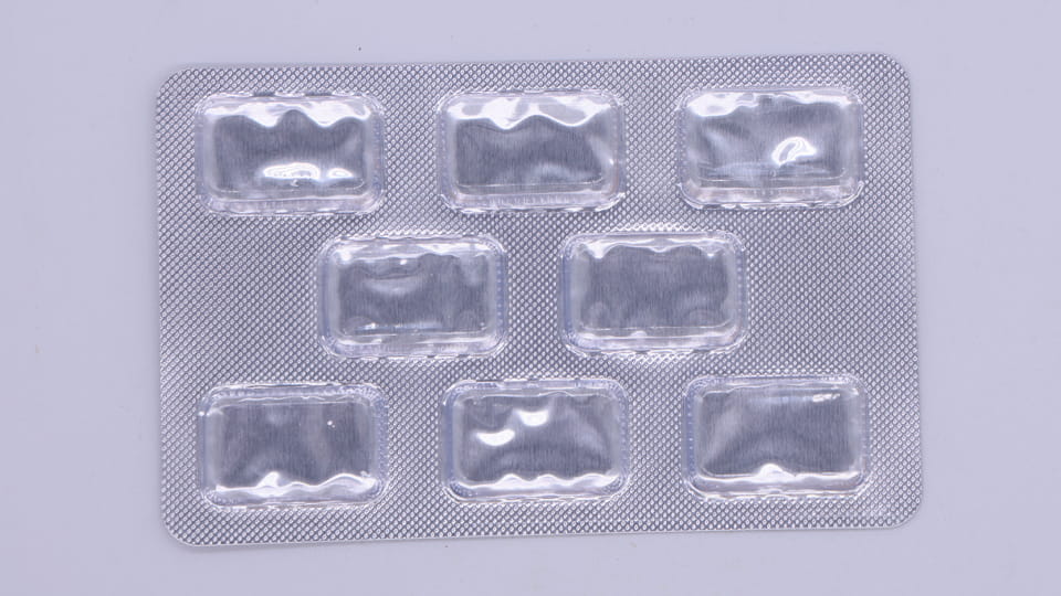
Empty thermoformed blister pack with nine clear cavities, illustrating the formed structure inspected during blister thickness measurement.


Where Does Blister Film Become Thinnest During Forming?

Certain areas in a thermoformed blister tend to thin more than others. Genel olarak, . deepest stretching zones end up thinnest, while un-stretched or lightly-stretched zones stay near the original gauge. Industry sources note a predictable pattern:

  • Flange (rim) and flat areas:These see little or no stretch and remain roughly 90–100% of original thickness.
  • Sidewalls:Vertical or tapered walls typically thin to about 50–70% of the original film.
  • Corners:The most severe thinning happens at corners, özellikle dıştan veya alt köşeler of a deep draw. In aggressive draws, these corners can be only 25–40% of the original film thickness.
  • Cavity bottom:If the bottom is flat, it may retain 60–80% of original thickness, but corners of the bottom often thin further.
  • Shoulder (upper transition):The shoulder where the sidewall meets the top of the pocket may thin moderately if deeply curved, but is often thicker than the bottom corners.
  • Web between cavities:The flat sheet (web) between cavities doesn’t form into pockets and keeps full thickness.

Keep in mind these are typical trends, not absolutes. The exact “weak points” depend on the specific boşluk geometrisi, beraberlik oranı, Ve forming conditions. Örneğin, a square cavity might have very sharp corner thinning, while a round cavity spreads the stretch more evenly. One blister design guide emphasizes that cavity dimensions and corner radii directly affect thin spot formation. Pratikte, you often find the thinnest film at the hardest-to-form spot – usually sharp internal corners or the deepest draw.


How to Measure Blister Thickness After Forming

Measuring the formed wall thickness requires precision tools and careful sample prep. There are a few common approaches:

  • Contact thickness gauge or micrometer:A calibrated digital thickness gauge (with flat anvils) or screw micrometer can measure a cut cross-section of the blister wall. Örneğin, one can carefully cut or punch out a strip through the formed pocket, then place the slice under the gauge (or between micrometer jaws) to read the local thickness. This direct-contact method is simple but destructive. The anvil of the gauge must be small enough (a few mm) to reach specific points like corners. ISO 4593 describes using mechanical scanning gauges for film thickness, but it explicitly states this is Olumsuz suitable for embossed or formed films. Başka bir deyişle, you typically measure a trimmed sample, not the whole bag with ISO 4593.
  • Optical/microscope measurement:Another way is to embed or tape the blister sample and examine the cross-section under a microscope or optical comparator, sometimes after polishing. The thickness can be measured on the image. This non-contact optical measurement avoids compressing the sample, but requires a good cut and equipment.
  • Ultrasonic thickness gauge:Ultrasonic thickness gauges can offer a non-destructive measurement option for certain plastic materials. Fakat, conventional contact ultrasonic gauges require acoustic coupling, and their suitability for small, curved blister cavities must be validated. Fakat, they need a fairly uniform path and coupling fluid, and most handheld models are optimized for flat parts. For a blister, you’d need to ensure good contact (even on a curved wall) and know the film’s sound velocity. It’s less common for blister walls.
  • X-ray or CT scanning:High-end labs or validation may use X-ray CT to map wall thickness in 3D. This is not routine in production but can verify thickness distribution on a sample pack.

In everyday QC, A digital thickness gauge or micrometer is most common. Örneğin, a 0–12.7 mm digital gauge with 0.01 mm resolution can measure plastic films accurately. You simply lower the probe onto the cross-section. Anahtar şudur: make flat, perpendicular cuts through the blister (using a scalpel or circular saw) so the gauge touches the true wall surface without bending it.

When taking measurements, ensure the tool is zeroed, the film is clean, and cut edges are perpendicular and undistorted. If a blister film is multilayer (beğenmek PVC/PVDC), remember you measure total thickness. You might average multiple readings at one point (gently lift and remeasure) to ensure consistency. Always note the measurement locations and conditions.

Pratikte, no single standard covers “finished blister thickness measurement for QC.” For instance, ASTM D6988 – a guide for film specimen thickness – explicitly says it değil cover sampling or QC methods for finished products. So your methods and criteria are typically defined in-house or by material specs. What’s important is accuracy and consistency in your measurement method.


Choosing Sampling Locations for Blister Thickness Testing

A critical part of thickness control is sampling at the right spots. Blister cards are large sheets that span the film width and run through the machine, so variation can occur in two directions: across the sheet (cross-web) and along the machine direction (infeed to discharge). A risk-based sampling plan should cover both dimensions and multiple cavities.

Consider sampling in these ways:

  • Across the web width:Measure at least in three lateral positions – left, center, and right edges of the film – because heating and die contact can vary across width. If your machine has multiple tracks (parallel rows of cavities), sample each track on the film. Örneğin, on a four-track machine you might measure one cavity per track across the width.
  • Along machine direction:Take samples at different times in the run – e.g. after startup, mid-run, and at the end. The material may heat up or the film tension may change over time, so thickness could drift. Sampling only at one point (like the first card) risks missing variation.
  • Within each cavity:On a given blister cavity, choose a few key points: typically one on a sidewall, one at a corner, and one at the bottom (or shoulder). If the blister has complex shape, more points may be needed. Often we care about the minimum local thickness, so include the obvious “thin zone” (like the sharpest corner) as a test point.
  • Number of cavities:Depending on batch size and risk, sample from multiple cavities on the same sheet or on separate sheets. For a large lot, pick random blister cards for inspection. A simple plan might measure one card from every X cards produced, checking a few points as above.

Örneğin, a QA team might measure thickness at left/middle/right on the first, middle and last card of a run, and within each of those cards measure 4 corners, 4 sidewalls, and the bottom. The exact sample count isn’t fixed by regulation; it’s typically based on an AQL or process capability decision. Anahtar şudur: span the whole sheet and process so you spot any pattern (örneğin. one side consistently thinner, or end of run drift).

Think of the sampling layout like a grid:

  • Cross-web positions:G. 0%, 50%, 100% of width.
  • MD positions:G. start, mid, end of a production lot.
  • Cavities:If the tool has 10 cavities across, pick a representative one in each group.

Önemli olan, treat your sampling plan as risk-based: focus on high-shear or deep-draw features. If a certain cavity or track is known to be marginal, include it every run. If new tooling or material is introduced, be more aggressive in sampling (örneğin. measure more points or cards). There is no one-size-fits-all minimum; whatever you do should be documented and consistently followed.


How to Establish Blister Thickness Acceptance Criteria

There is no single universal “cookbook” for acceptable wall thickness in blister packs. Each product and material can be different. Fakat, here are guiding principles for setting criteria:

  • Nominal thickness:This is the target or original film gauge (örneğin. 250 µm PVC). For non-formed areas (flange or cut-web), you typically allow a small tolerance (say ±5–10%) around that value. Örneğin, one QC guide rejects PVC film if more than 5% of points exceed ±8% of nominal. Ama unutma, . formed walls will usually be thinner than the nominal gauge.
  • Minimum local thickness:Instead of demanding everywhere meet nominal, focus on minimum thickness in critical zones. Identify the thinnest location (örneğin. a corner) in each blister and require it to be no thinner than a functional limit. That limit depends on your design and performance tests. Örneğin, if a crash test or leak test requires at least 0.1 mm of PVC at the corner to pass, then 0.12 mm might be your minimum threshold. Some companies specify a percentage of original (örneğin. “corners must be ≥40% of nominal”), but it’s safer to tie it to actual function (örneğin. mechanical strength or barrier).
  • Average or range:You may track the average thickness or the range (max–min) on a card. Some teams calculate the coefficient of variation (Özgeçmiş) = (standard deviation ÷ mean)×100% to quantify uniformity. A low CV (örneğin. 5–) means thickness is consistent, whereas a high CV indicates hotspots. Fakat, CV alone is not enough; always check absolute min values.
  • Material specification:Check the film supplier’s spec. They might give a nominal gauge and tolerance (örneğin. 250 ± 10%). Your formed part should reflect that, recognizing thinning. If the material spec says 250 ± 10 μm, you know original film under 225 μm is out-of-spec. Also consider multilayers: if PVDC coat is 50 μm on 250 μm PVC, the combined should be 300 μm nominal.
  • Function/performance:Nihayetinde, acceptance should link to product requirements. Örneğin, blister packs often undergo leak/penetration tests, humidity tests, veya mühür bütünlüğü testleri. If a blister with a certain thickness profile passes these tests reliably, that may inform your threshold. Some companies run studies forming intentionally thin parts to see failure points, then set limits just above that.

Be careful not to just copy flat-film tolerances. A blister cavity is like a different product than the flat sheet it started from. Örneğin, ISO 4593 and ASTM D6988 specify film measurement methods but explicitly do Olumsuz define pass/fail criteria for formed products. There is no ISO or ASTM standard that says “blister corner wall must be at least X μm.” Instead, use those as reference for gauge accuracy, and establish your own spec.

One practical rule: if the ortalama wall thickness (across all measured points) stays near the expected value (örneğin. within 5–10%), ve minimum thickness at the most-stretched point meets your design requirement, you’re likely in good shape. Örneğin, some quality groups accept blisters if all measured walls are within ±10–15% of the average thickness, and no corner is below a set fraction of nominal.

Nihayet, document whatever criteria you choose in a QC procedure. Make it clear which points are critical, what statistical bounds apply, and what to do if a batch fails. Örneğin, you might say: “Accept batch if ≥95% of measured points are ≥80% of nominal film thickness, and corners ≥75 μm” – based on your validation data. Always support criteria with a risk assessment or test evidence.

(Not: An illustrative acceptance table might list “Nominal = X μm, Tolerance ±Y μm, Minimum corner = Z μm, Özgeçmiş < 15%”, vesaire., but values depend on your product.)


What Causes Uneven Blister Wall Thickness?

Knowing what makes walls uneven helps you avoid thin spots in the first place. Common causes of thickness variation include:

  • High draw ratio:If the cavity is very deep relative to its opening (high H:D ratio) or the total area stretch is large, the film must flow farther, thinning more. Başka bir deyişle, more stretch = more thinning.
  • Sharp corners and poor design:A cavity with tight internal corners or abrupt transitions will locally stretch the film more. Generous corner radii (2–3× film thickness) and draft angles help distribute the material, while sharp corners concentrate thinning.
  • Düzensiz ısıtma:If the oven or heaters don’t warm the film uniformly, some spots may soften more and stretch differently. Cooler areas will form poorly, while overheated zones may thin excessively or even melt through.
  • Vacuum/pressure distribution:Incomplete vacuum coverage or pressure application can let parts of the film “hold back” or stretch unevenly. Örneğin, a vacuum leak in one area will keep that zone thicker.
  • Lack of plug-assist (for deep draws):For very deep cavities, without a plug (or mechanical pre-form), the film may stretch too abruptly when the vacuum/air is applied. A plug (a pre-form tool) pushes the film slightly into the cavity before final forming, evening out stretch. If missing, the corners especially will thin.

Özetle, any feature or setting that forces the film to “pull farther or faster” will create thin spots. Manufacturers often emphasize that excessive draw ratio is the root cause: if your design requires an extreme stretch, even thick film will thin out (and may tear).

Environmental factors like ambient humidity have little effect on film thickness (though moisture can affect strength or lamination). Tension control on the web can matter: too high tension can over-stretch the film into the pocket; too low can cause wrinkles and local thick spots. But tooling and heat are usually bigger drivers of uniformity.
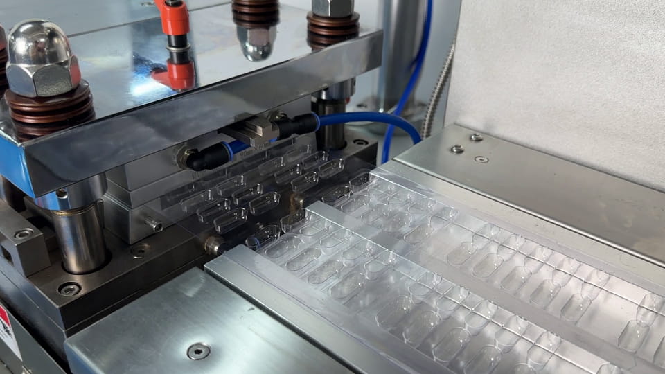
Blister thermoforming machine forming plastic film into cavities, illustrating how forming conditions and tooling can affect blister wall thickness uniformity.


How to Improve Thickness Uniformity in Blister Forming

If measurements show problematic thin zones, there are several levers to pull:

  • Redesign the cavity:Increase the opening or decrease depth to lower draw ratio. Add larger radii or fillets at corners. Even small increases in corner radius (örneğin. 0.5 mm more) can significantly boost local thickness.
  • Use plug-assist:For deep blisters, adding a foam or polymer plug that pre-stretches the film into the cavity can dramatically equalize thickness. Studies show corners that might be 30% of original thickness can be raised to 50–60% with plug-assist. If your cavity depth ≥ width, a plug is strongly recommended.
  • Optimize heating:Ensure the oven or heating panels are set for uniform temperature. Preheat thicker zones if possible, or adjust heater distance. A well-calibrated temperature profile yields more even forming.
  • Adjust vacuum/pressure cycle:A slower ramp-up (gradual vacuum increase) gives film time to flow. Use a so-called “dwell” time where film is held in the cavity before cutting, so it relaxes. Make sure the vacuum line is clean and the chamber seals properly.
  • Tune film tension:Set the web tension so it just supports the film without stretching it before forming. Many machines allow adjusting roller tension or brake settings.
  • Select proper film:If thinning is a chronic issue, use slightly thicker starting film (within spec limits) or a film with more elasticity. Fakat, thicker film alone is not a fix; a very thick sheet will still thin if overstretched.
  • Maintain tooling:Check the forming mold for damage or wear. A gap or nick could cause uneven contact. Keep the mold surfaces clean and release agents even.

Whenever you make a change, re-qualify. Örneğin, if you add plug-assist, re-measure the formed thickness to ensure corners improved. Kural olarak, “try the design/process fix, then re-form and measure before approving”.


Blister Thickness Measurement Checklist for QA/QC Teams

To keep measurements reliable, follow a consistent procedure. Here is a sample checklist for each thickness check session:

  • Instrument Prep:Calibrate the micrometer or thickness gauge just before use. Zero it on a reference block or the unformed web. Check that the foot is clean and the measurement surface is flat. If using an ultrasonic gauge, verify the sound velocity or use a calibration standard of known thickness.
  • Sample Handling:Wear soft gloves to avoid contaminating or stretching the film. Remove a formed part carefully – do not tear it off abruptly or it may stretch the material. Let the part relax on a flat surface for a minute if it was under tension.
  • Ambient Conditions:If indoors, ensure room temperature is stable (some plastics expand/contracts with temperature). The film should be at the same temperature it will see on the line (usually around 20–25°C ambient). Humidity is less critical for PVC but note in records if conditions are extreme.
  • Measurement Points:For each cavity you sample (bölüme bakın 4), record exactly where you measure: örneğin. “Lane 2 – Cavity B2 – Bottom center = ___ µm; Sidewall mid = ___ µm; Upper corner = ___ µm.” Use consistent wording or a diagram reference so it’s clear to anyone reading the log.
  • Apply Correct Technique:Lower the gauge foot gently until it touches the film – avoid bouncing or oscillating. If using a spring-loaded gauge, let it settle before reading. For hand micrometers, close slowly and watch for the feeler to click firmly. Take 2–3 readings per point and average them (especially if you hear click noise).
  • Verify Flange (Baseline):Always measure the flat flange (unformed rim) thickness as well. This checks that the film gauge itself is as expected. If the flange reads off-nominal by a lot, your incoming film might be out of spec – investigate separately.
  • Record Data Promptly:Write down or log each measurement immediately. Include the part ID, date/time, operator name, instrument ID, and calibration status. Good data practice: everything is traceable.
  • Compare to Spec:As you log each value, flag any reading below the minimum acceptance limit you established. This will make it obvious if a check fails. Örneğin, highlight any corner measurement under 100 µm if that’s the cutoff.
  • Periodicity:Apart from initial setup runs, decide how often to sample during a long production. Örneğin, a line might do a quick check every 30 dakika. If process controls are robust, sampling frequency could drop to once per shift – but do it more often if running new product or when changes occur.

By following a disciplined QA routine, you ensure measurements are consistent day-to-day. Any trends (örneğin. gradual thinning of all cavities over time) become visible in the records, prompting preventive action.


Çözüm

Measuring blister wall thickness after forming is essential for ensuring blister pack quality and patient safety. The formed walls can be much thinner than the raw film (sometimes only a quarter of the original at sharp corners), so targeted thickness checks catch potential weak spots. Key takeaways: use proper gauges or microscopy to measure cut samples (recognizing that ISO standards cover only flat film), sample strategically across the card, and define acceptance based on design needs rather than guesswork. Focus on the minimum local thickness at critical points and maintain a realistic tolerance (often ±10–15% around nominal average). Remember that no single standard governs blister thickness – you must tailor your criteria to the specific materials and product.

If you encounter persistent thin spots or variability, look upstream: review your blister cavity design, beraberlik oranı, heating uniformity, and consider process aids like plug-assist. Improving uniformity often comes down to better mold design and process control, not just more expensive film.

For pharmaceutical manufacturers evaluating kabarcıklı paketleme ekipmanları, the forming station, heating system, mold design, and material-handling configuration all deserve attention. Jinlu Packing provides pharmaceutical blister packaging machinery solutions designed to support efficient and consistent packaging production. Ekibimizle iletişime geçin to discuss your blister packaging requirements and equipment options.


FAQs on Blister Thickness Measurement

How do you measure blister thickness after forming?

Formed blister thickness can be measured using a suitable digital thickness gauge or micrometer on accessible areas. Cross-sectional microscopy is useful for detailed measurement of curved cavity walls, corners, and other critical locations. The method should be validated for the material and sample geometry.

Why does blister film become thinner after thermoforming?

Thermoforming heats and stretches plastic film into a cavity. As the material covers a larger surface area, its thickness decreases in stretched regions. The degree of thinning depends on cavity geometry, beraberlik oranı, malzeme özellikleri, heating conditions, and forming method.

Where is the thinnest point in a formed blister?

The thinnest point depends on the cavity design and forming conditions. Deep corners, sidewalls, and bottom transitions are common areas requiring attention. Manufacturers should perform thickness mapping to identify the actual minimum-thickness location rather than assume one fixed location is always thinnest.

What causes thin spots in blister packaging?

Common causes include excessive cavity depth, keskin köşeler, uneven heating, improper vacuum distribution, and inadequate plug-assisted forming. Material properties and web alignment can also influence thickness distribution.

What is the minimum wall thickness for pharmaceutical blisters?

There is no universal minimum wall thickness for all pharmaceutical blister materials and cavity designs. Manufacturers should establish minimum local thickness requirements using material specifications, boşluk geometrisi, mechanical performance, and appropriate packaging validation data.

How many points should be measured on each blister cavity?

The number of measurement points depends on cavity geometry, process risk, and validation results. A thickness-mapping study should initially cover critical areas such as corners, sidewalls, and the cavity bottom. Routine inspection can then focus on the locations identified as most critical.

Can a digital micrometer measure formed blister thickness?

Evet, provided the measuring instrument can properly contact the intended surface without compressing or deforming the sample. Conventional micrometers may not be suitable for small or sharply curved cavity locations. Cross-sectional microscopy can be used when more detailed measurements are required.

What is the difference between incoming film thickness and formed blister thickness?

Incoming film thickness refers to the thickness of the original flat material before forming. Formed blister thickness refers to the local wall thickness after the material has been heated and stretched into the cavity. The two values can differ considerably because of material redistribution during thermoforming.

How does cavity depth affect blister thickness?

Greater cavity depth generally increases the amount of material deformation required during forming. Depending on cavity geometry and forming conditions, this can increase local thinning in the sidewalls, corners, or bottom regions.

How can manufacturers improve blister thickness uniformity?

Manufacturers can improve thickness consistency by optimizing heating conditions, reviewing cavity geometry, adjusting plug-assisted forming where applicable, maintaining vacuum and pressure systems, and controlling web tension and alignment. Thickness should be remeasured after process changes to verify the results.


Referanslar:
1.Plastics — Film and sheeting — Determination of thickness by mechanical scanning —— ISO 4593:1993
2.Standard Test Method for Determining Plastic Film Thickness and Thickness Variability Using a Non-Contact Capacitance Thickness Gauge —— ASTM D8136-24
3.Evaluation of the Thickness and Oxygen Transmission Rate before and after Thermoforming Mono- and Multi-layer Sheets into Trays with Variable Depth —— MDPI Polymers
4.Termoformda et kalınlığı dağılımının belirlenmesinde tapa tasarımının rolü —— WILEY Çevrimiçi Kütüphane
5.Oxygen barrier properties of Thermoformed trays manufactured with Different Drawing methods and Drawing Depths —— WILEY Çevrimiçi Kütüphane
6.Determination of the thickness of plastic sheets used in blister packaging by near infrared spectroscopy: development and validation of the method —— Bilimsel


Bu Makaleyi Paylaş:
Resim Küçük fu
Küçük fu

Küçük fu, Jinlupacking'in kurucusu, getiriyor 20 ilaç makineleri sektöründe uzun yıllara dayanan uzmanlık. Onun liderliği altında, Jinlu, tasarımı entegre eden güvenilir bir tedarikçiye dönüştü, üretme, ve satış. Petty, müşterilerin ilaç ambalajının karmaşıklıklarını aşmasına yardımcı olmak için derin sektör bilgisini paylaşma konusunda tutkuludur, sadece ekipman almamalarını sağlamak, ancak üretim hedeflerine göre uyarlanmış gerçek bir tek elden hizmet ortaklığı.

İçindekiler

Sorgunuzu Gönderin

Bir yanıt yazın

E-posta adresiniz yayınlanmayacak. Gerekli alanlar * ile işaretlenmişlerdir

Ücretsiz Fiyat Teklifi Alın

*Gizliliğinize saygı duyuyoruz ve tüm veriler korunuyor. Kişisel verileriniz yalnızca JL çözümü için kullanılacak ve işlenecektir..